
|
|||
|
Jeep FAQ How-To Articles Quick Reference Product Reviews My Buildup Random Home |
Well next in my do it yourself series, will be a round of sensor testing. I'll be starting out with Throttle Position Sensors. TPS sensors tell the ECM how far open the throttle is. All it does is vary resistance as the throttle is opened up. For this test the TPS doesn't necessarily have to be off the Jeep, but I think it's a little easier to do off the Jeep. You will need a multi-meter though. If you aren't familiar with multi-meters, take a look at my Multi-Meter Basics Most TPS sensors have three pins; it varies in resistance in both directions, both up and down in resistance so the ECM has two readings to compare for accuracy. Here is the pin configuration on YJ TPS sensors:  Here is the pin configuration on TJ TPS sensors:  Start by measuring the resistance between pins 1 and 2. 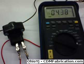 Use a large screw drive to turn the TPS sensor slowly. 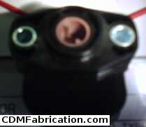 On a YJ TPS the resistance on 1 and 2 the resistance should roughly go from 0-5. On pins 1 and 2 on the TJ TPS, the resistance should go from 5-0. The YJ one I tested went from 0.417 - 4.58, however more importantly you are looking for dead spots, if you reach a point where the meter drops off or jumps there is a problem. There should be a nice smooth increase or decrease in resistance. Repeat the same test on pins 2 and 3. On a YJ TPS pins 2 and 3 should go from 5-0. On a TJ TPS, pins 2 and 3 should go from 0-5. The resistance pins 2 and 3 maybe a little different than they were on 1 and 2, for example my YJ TPS went from 4.38 - 0.0236 in this direction.
© Copyright 2006 - 2025 Mike Lee
|
|
|