
|
|||
|
Jeep FAQ How-To Articles Quick Reference Product Reviews My Buildup Random Home |
Ok this is just the start of this writeup, I will be continuing it over the next few months as I continue my Camaro buildup, adding stuff and going into more detail. When rebuilding a motor you have all sorts of options. You could just buy a complete motor, but when it comes to motors, I trust no one, I want to know exactly what's been done. Now there are both upsides and downsides to building your own motor. The biggest downside to building your own, is you pretty much have no warranty, if something goes wrong, it's coming out of your pocket. That's why everything you assemble needs to be double and triple checked to make sure it has been machined right. The biggest upside to buying a crate motor or letting a machine shop do all the assembly for you is that you will get a warranty with the motor. The downside with this is the cost, it will undoubtedly cost you a fair amount more. Besides saving money building your own motor will allow you to do some other things to make it a little more special, and as an added bonus you do get a sense of accomplishment of building something. Before you go to the machine shop I wish I would have taken more pictures of it before I took this block to the machine shop, but I"ll do my best to help explain what to look for, and things to do before you take it to the machine shop. Start by inspecting the cylinder walls. This is a closeup of one of the cylinders, notice the cross hatching on the cylinder walls, that's a good thing, it should go from top to bottom. Rub your finger up the cylinder wall in particular at the top of the block, there should not be a ridge. If there is a big ridge you may need to use a ridge reamer before removing the pistons. If the ridge is just barely noticeable, you can most likely get away with just honing the engine. If the ridge is fairly noticeable, the block should be bored, and then finish honed. 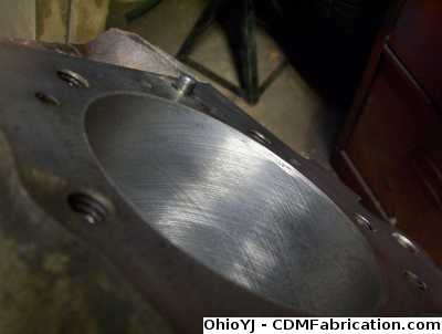
Next you can remove the pistons and rods. Make sure you mark the rods to ensure they get placed back in the same spot they where. Once the rod bolts have been removed, gently remove the caps, never beat on them, and make sure if you smack anything to make sure you aren't using anything metal. Place a small piece of 3/8 fuel hose over the bolts of the rods, before removing them, to protect the crankshaft. 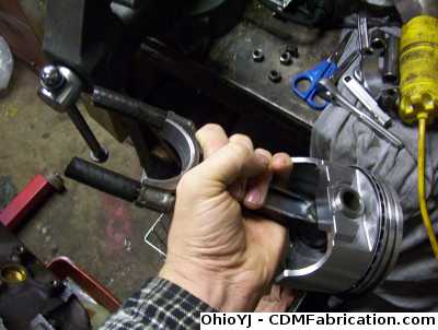
Once you have the rods out, inspect the bearings for any abnormal wear. Then remove the bearing. You should also see cross hatching in the rod ends, like below. Any weird marks here, you may want to consider having your rods reconditioned. 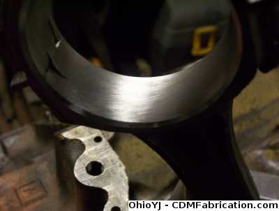
Inspect the piston skirts for abnormal wear. They will always have a few scratches, but if you have a bunch of rub marks, and scratch marks, I'd say you're best have the block bored, as the piston maybe rocking around in the cylinder a bit too much. 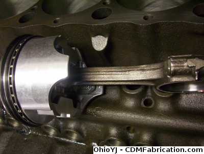
Once all the rods are removed, time to remove the main caps. Make sure you keep track of the main caps, they need to be returned to the same exact spot you removed them from, in the same direction. If you mix them up, you'll have to have the mains line bored, and honed. Run your fingernail across the crankshaft journals, they should be completely smooth. A little bit of sludge build up will be in between the rods, so clean the crank, then check it for smoothness. If its rough at all, it should be turned, and then polished. If its smooth, and I mean perfectly smooth, you can get away with just polishing it. 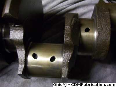
If the block has sat for any length of time, its likely the lifter bores will need honed. If a lifter has failed, or has a bunch of weird marks on it, you may even need to have a lifter bore sleeved, this is something you'd want a machinist's opinion on. 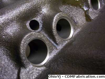
If you are just honing the cylinder walls you can re-use the pistons assuming they aren't damaged. Most engines use a pressed in center pin, and so a machine shop must press and replace the pins to replace the pistons. If you are boring the motor you must buy new pistons. At the very least, you should have the machine shop hot-tank or clean the block and install new cam bearings. I had the machine shop, turn and polish the crank, clean the block, bore and hone, install cam bearings, install freeze plugs, install new pistons on the rods, and consider milling the deck to ensure its flat and clean. Now you can easily do the freeze plugs, but most machines shops do this for next to nothing, so I let them do it. Starting Assembly This step can be time consuming, the main thing is don't get discouraged. Normally if you have all the pieces, and everything goes right, you can build the motor in a day, but things happen. This motor, has been partially assembled, and then disassembled eight times now because of problems. Everything needs to be double checked, it needs to be perfect when it goes together. Once you get the block and parts and pieces back from the machine shop, get ready to clean it again. Spray everything down with brake clean, and wipe it down. Once you think you have it clean, clean it some more, then once it clean, clean it one more time. Everything needs to be spotless. In the past I've used assembly lube on the bearings and such, but a man much wiser than me, suggested against it on this build, and I'll be using just standard motor oil, and very little oil at that. The engine will be primed after assembly so it will be properly oil before actually starting. The camshaft is the one exception, an assembly lube, or preferably Lucas assembly lube must be used. Once you have it clean, set the main bearings in the block. 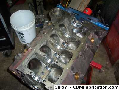
Then set the crankshaft in place carefully. No oil should be used at this time. You'll need some green plasti-gauge to check the bearing tolerances. Just set small piece of green plasti-gauge on each of the crankshaft journals (its the thing that looks like green dental floss in the picture). Then install the bearings into the main caps, and torque them down to their specified torque. As always go in steps, on this motor 65 ft-lbs is the final torque, but I started by torquing the bolts to 35 ft-lbs, then moving to 65 ft-lbs. 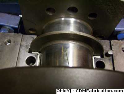
Now remove the bearing caps, being careful not to spin the crankshaft at all. The tighter things are the more the plasti-gauge will be smashed. Compare the plasti-gauge to the chart on the package. Racers typically shoot for 3 here, looser motors equal less Resistance, and less chance of spun bearings, there is however a trade off, as the motor will have a shorter lifespan. Mine all came out about 2.5, not quite 2, not quite 3 on the chart. Every motor has different specifications, you don't want it too tight, 2 - 2.5 would be more ideal for most motors. 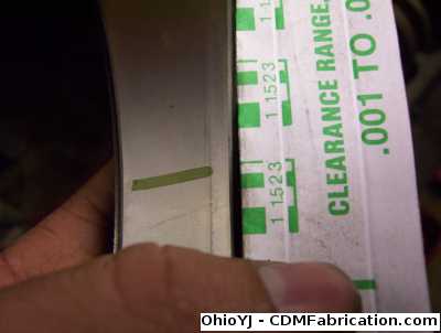
Once you've checked all the main bearing tolerances, clean off the plasti-gauge, put a small amount of oil on the bearings, and re-install the caps. Diesel oil is great for this purpose, Mobil DelVac is a prefered choice at this point, because of it's zinc content, and easily found at most parts stores. The crank should rotate easily and smoothly at this point. 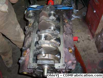
It's time to prep a pistons for installation. Place small pieces of rubber hoses on the rod studs to ensure they can't score the crankshaft when they are installed. If you bump the crank at all with the rod bolts or an edge of the rod you must stop and polish the imperfection out. Again the rod bearings must also be plasti-gauged which means they should be installed dry at first.
Then properly place the rings. When installing the rings, carefully read the instructions that come with them, they go on in specific order, and usually have a top and bottom. Some will also tell you how to place the gaps. On this motor, the piston ring gaps, should be 180 degrees from each other. Notice the notch in the edge of the piston, this always goes towards the front of the motor. 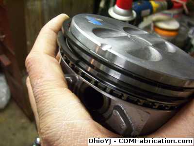
Notice that the rods have one edge that is rounded more than the other. This rounded edge always goes towards the main cap its closest too. 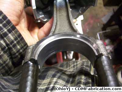
Then place the piston ring compressor around the top of the piston. 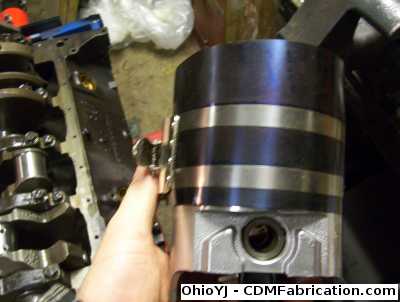
This is the one place its ok to use a fair amount of oil, you need to coat the cylinder wall to ensure the piston doesn't scratch it when being installed. You can also put some oil on the piston skirt as well if you wish. 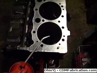
Gently place the piston in place. Holding the piston ring compressor firmly against the deck of the block, take a block of wood, or the end of a dead blow hammer and smack it downward. Hit the piston like you mean it, but remember you aren't trying to smack it through the other side. If it doesn't go all the way in the first time, smack it lightly, if it stops moving, pull it back out and start over, sometimes the rings will get caught between the compressor and the block. It's best to have a helper guide the rod down over the crankshaft. 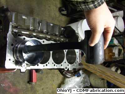
Now its very time consuming, but you'll need to install each rod dry, torque it down, then remove the cap without rotating the crank at all to plastigauge the rods too. I ran into a situation where one rod was 0.003" smaller than the rest, that 0.003" was enough to make the bearing tolerances way to tight, and the motor would not spin at all. That rod must now be re-machined. If the plastigauge shows the bearing tolerances to be within spec, remove the cap, and re-install the hoses over the rod bolts, bump the piston down some to put a small amount of oil on the rod bearings, then tighten everything back down. When tightening the rod caps down, you need to have a brass feeler gauge in between the rods. Every motor is a little different, but typically I use 0.008" feeler gauge. I usually use two feeler gauges on each side of the crankshaft, usually a 0.006" on one side and 0.008" on the other. 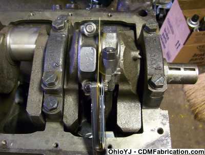
Once you have two rods installed, try and turn the motor over, it should rotate with a little resistance. If the motor won't budge, stop and take it back apart. Even a small speck of dirt will keep the motor from turning over. As you add rods and pistons the assembly may get a bit stiffer, but it should still turn. Keep doing this everytime you add a rod, give it a brief turn back and fourth to ensure it still moves freely. Now since we are dealing with pieces that have been machined every which way, it's best to go through and check a few more things. Once you have two rods and pistons installed, its time to check deck clearances. Now there is a special tool that holds a dial type feel gauge above the piston, but I'll have to settle for a slightly less sophisticated method. I'm holding my dial calipers as level on the deck as possible and then measure how far down the piston is at TDC (top dead center). My rough measurement came out to be 0.021" in the hole. After doing some quick calculating, this should result in roughly a 10.7:1 compression ratio. Generally as long as the piston doesn't come above the deck you are ok. 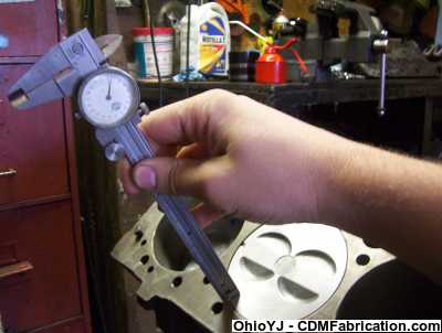
Once you have all the pistons installed, it's time to install the camshaft. You want to very generously apply a good assembly lube, like Lucas's assembly lube to all the lobes of the camshaft, and where the bearings ride. It can be tricky to install the camshaft because you have to slide it in holding it perfectly straight, it will scratch the bearings easily, you must try your best to avoid damaging any bearings while sliding it in. Once the camshaft is in, you can install the timing chain. Usually you must first install the wood-ruff key into the end of the crankshaft as the machine shop typically will remove them and hand them back to you.The timing chain must be slide on straight together complete. Make sure your timing dots are aligned with each other. Now we are finally getting somewhere. Hopefully you had your lifters soaking in oil for a few days. You can now install the lifters, however before doing so wipe the oil from the bottom of them, and apply a dab of assembly lube first. Once all the lifters are in it's time to check piston to valve clearance. Now even if you are building a stock motor, it's better to be sure you have enough valve clearance than to find out later, your cam timing is off, or your pieces have machine too much and you no longer have enough clearance. Place a piece of modeling clay on the piston, where the valve where contact it. It should only be on half the piston, I just threw that big piece on there for a photo. Then using an old head gasket, (if you use your new one, you'll have to buy another, head gaskets are a one time use item), you need to bolt the head on. Ideally you need to torque the head down, just as if you where actually installing it permanently, but usually I just tighten it down with a small ratchet, not that tight, just snug. Then install two pushrods on the cylinder with the clay, and two rocker arms. Once you have the head bolted down, spin the motor over. Now if your clearances end up very close, then you will need to go back and do it again actually torquing the head all the way down just to double check. The reason I don't like torquing the head bolts down to check piston to valve clearance unless it's very close, is generally most are one time use as well, so normally it's best to use an old set for this as well. Then remove the head, and cut the clay in half where the valve compressed it, and measure it. Anything over 0.010" is plenty. If what you have is 1/8" - 1/4" you have gobs of room, don't worry about getting an exact measurement. 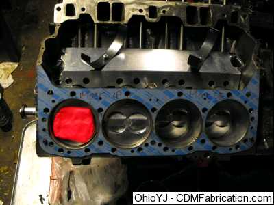
Make sure you clean any clay off the piston and head. Then it's time to clean the deck of the block and the head with brake cleaner. If you think it's clean go ahead and spray it down one more time, then install the new head gasket. Gently place the head on it. On some motors you must use thread sealant on the head bolts. Check for any instructions that came with the head bolts, as if they don't need sealant, some manufacturers will recommend oil on the threads before torquing them. If you bought ARP bolts, they generally supply special grease to be used. Remember there is a specific order to tightening the head bolts, notice my cheat sheet sitting on the motor showing me the order to tighten the 17 head bolts on this motor. As always go in steps, on this motor 65 ft-lbs is the final torque, but I started by torquing the bolts to 35 ft-lbs, then moving to 65 ft-lbs. 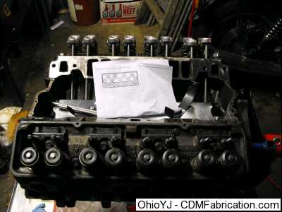
You can now slide the push-rods in, if you are reusing the old ones and they are hollow make sure you thoroughly clean them out. Then time for the rockers. And bolt down the rest of the rocker arms. All motors are different, on how the rockers are adjusted, so you'll need to check a manual for how to do this for your motor. Generally too the lifters need to be pumped up to properly adjust the rockers, which means the oil system will have to be primed. Rebuilding the Heads There's not much to the cylinder heads, but they do require some attention. If the heads are aluminum you should definitely have them milled to ensure they are perfectly flat, even if they are cast iron, you should still consider having them milled. If you have a bunch of miles on your motor, or a high lift cam, you should really replace the valve springs. They are inexpensive and easy to replace. If you have changed camshafts, make sure you order the valve springs recommended for your camshaft. Valve springs make a huge difference. Using a valve spring compressor, remove all the valve retainers. Typically I use a magnet to pull the valve retainers out. Usually you have to compress the spring, press it down, then smack the valve with a dead blow hammer to free the retainers. Careful though the valve retainers can go flying out, and they are a pain to find. Either leave the magnet next to the valve to try and catch the retainers, or use a big plastic cup over the compressor to keep the retainers contained. They don't come out with any force, and normally they don't just go flying, but they can, and because they are so small they are hard to see on the garage floor. 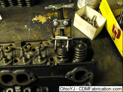
Make sure you keep all the valves and springs in order. The valve seals generally will just pop off. You'll want to install new ones before final assembly of the head. The next step is to lap all the valves. Even if they just came back from the machine shop, it's best to double check their work. In the picture below you can see two valves, the one of the left has been lapped, the one on the right has not, also notice the valve seats on the heads. 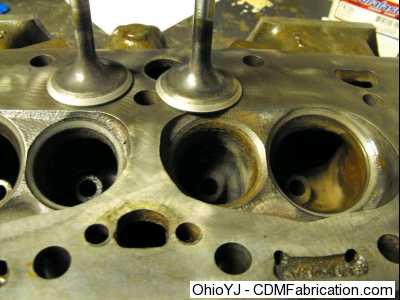
When you lap the valves, you should also be able to see where the valve is actually seating, and sealing. It will not seal around the whole seat, you should be able to see a grey ring around the valve, hopefully towards the middle on the valve, that will be where it is sealing. If your ring is not even, or does not go all the way around the valve, somethings not right. To lap the valves, simply apply some valve grinding compound to the valve in a few different places. Then apply some oil to the valve guide and the valve, and slide the valve into the head. 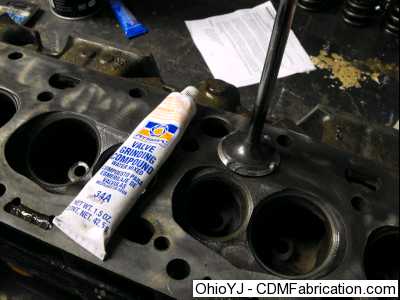
They sell suction cups with wooden handles that grip the valve, that you spin in your between your hands, but this can take a while. I'm using a drill to spin the valve. WARNING! I'm using a copper shim between the valve and the drill, the drill chuck can damage the valve, you need some sort of shim between the two to protect the valve. I'm not using the key to tighten the drill down, I'm just tightening it by hand. Also note you still aren't spinning the valve at a high speed, still spin it relatively slowly, and apply some pressure to the valve to make sure it's fully seated. Every so often lift the valve some and pull it back down. Using this method it typically takes 30 seconds or so per valve. Don't be afraid to apply more compound it you are getting weird results and try it some more. Now remember if you don't have any copper, brass, aluminum, to make a shim, you'll need to lap the valves by hand using the wooden dowel and suction cup method. 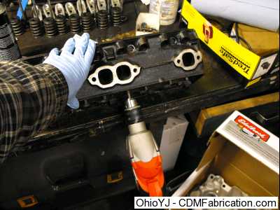
After lapping the valves, make sure you thoroughly clean all the valve grinding compound off, it is very abrasive. Slide the valve in first, again placing a small amount of oil on the valve guides. Then place the protective plastic sleeve over the valve stem, this sleeve comes with the new valve seals. Spray a small amount of oil on the valve seal and press it over the valve and down onto the head. Typically different valve seals are sold for intake and exhaust. I typically use the intake seals on both intake and exhaust, as they are nicer. Teflon seals are the top notch ones, but the premium intake seals that FelPro sells will work fine. Once you have all the valve keeps in place, go ahead and give each valve a smack with a dead blow just to make sure everything is seated and installed properly. 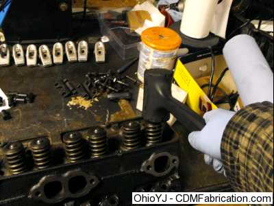
Making it Special, Optional Stuff You should consider chamfering all the oil passageways in the crank. This will get rid of all the thin edges on the crankshaft, which could break off inside the motor. This will also increase the area in which oil is released. This should be done prior to having the crank turned or polished. Anywhere you grind on the crank you should cover with tape, just to ensure you don't make any mistakes. 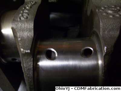
Check the oil drain back wholes. These areas are typically just cast, and have sharp edges and slag that can break off. The center hole in the picture is for the distributor, the other two are drain back holes. Feel free to grind on these some and enlarge them, and remove any slag you might find in them. 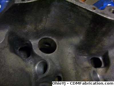
On top of enlarging all the drain back holes, I polished the lifter valley area, and grind it in way to direct oil towards the drain back holes. Now this is a fair amount of work, and should be done before the block is taken to the machine shop to be cleaned so all the dust will be cleaned out. 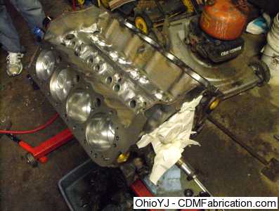
The front plugs of the oil passage ways from the factory are just press in plugs. Since these press in plugs can come out (not a common problem, but it could happen), I tapped the passageways for pipe plugs to prevent them from being able to come out. 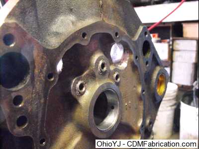
I had to cut oiling grooves in the front of the block, for the cam thrust washers. The tape is help prevent any accidents while cutting the oiling grooves. 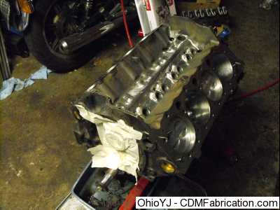
If you are going for ultimate in strength you can polish the rods, but only if you are going to have them shot-peened afterwards, and then have the whole rotating assembly balanced. Personally I skipped this step, as this is a budget build. To polish the rod, you grind off the seam that you see on the edge of the rod, till its smooth. 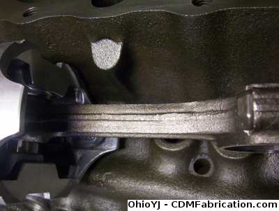
Check the valve reliefs for sharp edges. Any sharp edge will create a hot spot, and cause detonation. Here is a new piston, which has very sharp edge to it: 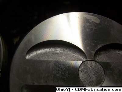
This is after I smoothed it out some, and rounded the edges of the valve reliefs. 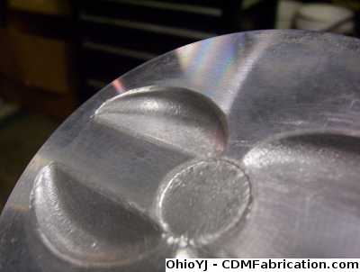
Next I actually polished the tops of the pistons. I started with 400 grit sandpaper, then 600, then 800, then polishing compound, then finished it off with some plastic polishing compound. This will help prevent detonation. 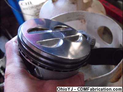
When a machine shop balances the assembly, the make sure all the pistons weigh the exact same amount, then they balance each side of the rod. This provides a much truer balance. Now again this is a budget build, so I didn't pay the machine shop to balance the rotating assembly. So I chose to improvise a little. 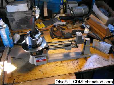
First I weight all the pistons and rods, and wrote the measurements down, notice the numbers on the box, they are weights. 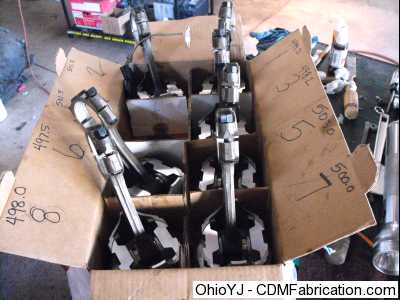
Then I carefully ground some of the material off the bottom of the pistons to make the heavy pistons match the lightest one. Note that I only had to debur the edges of the pistons on some of them to take off the proper amount of weight. It doesn't take much the parts should be pretty close to the same weight to begin with. 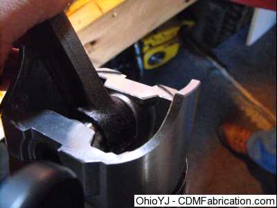
Once I had the bearings in place, I found that the block had 0.250" oil passageways, the bearings had 0.180" oil passageways. While you don't have to enlarge the holes in the bearings, I chose to, this will ensure plenty of oil reaches the bearings. You have to do this very carefully though, there can't be any burrs or rough edges. This can be tricky, any imperfections sticking up and bad things will happen. 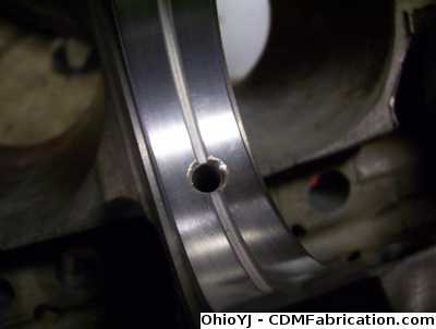
These aren't available for all motors, but in the picture you'll notice there is a lifter valley pan installed. This keeps hot oil from splashing on the bottom of the intake, and more importantly, if a push rod or rocker arm fails, the lifter isn't launched out of its bore, it's retained, and the motor will keep oil pressure. These pans can be a pain to install though, as you will have to install the pushrods, to make sure they clear. Then most likely you will remove the pan and push rods what seems like a hundred times to trim the pan to make it fit properly. 
If you are building a forced induction motor, or high RPM motor, studs maybe necessary, they increase the strength a considerable amount. I installed main studs to this motor only for a windage tray. 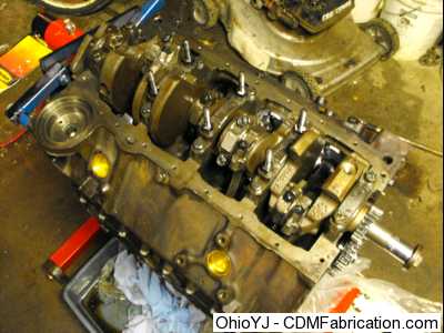
Here is the windage tray installed, these are generally worth a few horsepower. If you install a windage tray make sure you first ensure the oil pan fits over top of it. On this motor I had to drill two holes in the oil pan baffles to clear the main studs. Also most importantly make sure you oil dipstick clears, you may have to slightly bend it, you may have to drill a hole in the windage tray. If you have to drill or grind on the widage tray, obviously remove it from the motor first. 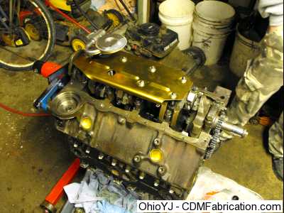
Now on this motor the oil filter adapter has a bypass built in. This allows unfiltered oil to enter the motor, which can be handy if the oil filter actually becomes clogged. However if the bypass spring is weak it can allow unfiltered oil into the motor. Race shops sell these without the bypass, but I modified the stock one to eliminate it. I simply popped the spring and plug out, and tapped the adapter for a pipe plug. The downside to this is the increase pressure can be a problem with cheap filters, and premium oil filters become mandatory. Also you should note that if you expierence a drop in oil pressure, try changing the oil filter, I've heard of people having to change filters once a month after doing this when running cheaper filters. 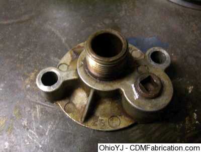
On this engine, the oil pump pickup is just pressed into the housing. Most hot-rodders will tell you to braze a strap to the pickup, or braze the pickup to the pump. I decided to heat the oil pump housing a bit, and put a tack weld on the pickup. The main goal is to keep the pickup from rotating, as its in there pretty good, it typically wouldn't just come out. 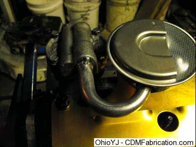
I had an issue with the timing marks not lining up on my gear drive. I ended up putting an 8 degree advance bushing in the cam gear to get the timing marks to line up. Something wasn't right so I had to pickup a cam degree wheel. This helps you determine exactly when and where the valves are opening and closing. Then by comparing the numbers that you get to the cam specs, you can determine the cam timing. Mine with the 8 degree bushing in it, ended up being 8 degrees advanced, so I had to put the standard bushing back in, and I know that the timing marks just don't line up for some reason. Cam timing has a huge impact on where power is made, so this is important. 
It did take us 4 pages of math and diagrams though to figure out that the cam was 8 degres advanced. 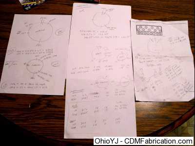
To be continued.......
© Copyright 2006 - 2025 Mike Lee
|
|
|